Simple Beam
Published: 28/05/26, Updated:
Version: 1.0.0
Calculation performs the analysis of the simply supported steel beam under various loading and support conditions and returns analysis results in various graphical and tabular format.
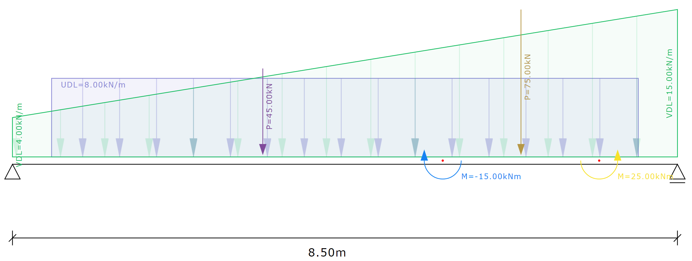
Input example for simple beam
Assumptions
The following assumptions are considered in analysis:
The crossection of the beam has constant E and I for the entire span length.
Beam is assumed to not develop any excessive deflections.
Stresses are assumed to be elastic.
Orientation for propped and cantilever supports is fixed as shown in loading diagram.
Distance to maximum moment is where shear is equal to zero and distance to maximum deflection is where slope is zero.
All loads entered are assumed to be at ULS and no factors are applied in an analysis.
Limitations
The calculation has the following limitations:
The support conditions are limited to simple, propped, cantilever or fully supported.
Steel sections are selectable from input dropdown and are not adjustable.
Input types can be as unifirmly distributed loads (UDL), variable distributed loads (VDL), point loads (PL) or moment load (ML).
The input loads are limited to 25 loads per load type.
| Input Variable | Description | Limits |
|---|---|---|
| L | Beam Span | 0 < L ≤ 10 |
| Section Type | Section Type | UKB, UKC, UKPFC |
| Section Designation | Section Designation | e.g., 203x102x23.5 |
| Iy | Moment of Inertia about the main axis | Iy > 0 |
| Include Self Weight | Include Self Weight | True or False |
| wsw | Beam Weight per unit length | Beam weight > 0 |
| Result Variable | Description |
|---|---|
| RA | Left Support Reaction |
| RB | Right Support Reaction |
| Vmax | Maximum Shear Force at |
| xVmax | Position of Maximum Shear Force |
| Mmax+ | Maximum Positive Bending Moment |
| xMmax+ | Position of Maximum Positive Bending Moment |
| Mmax- | Maximum Negative Bending Moment |
| xMmax- | Position of Maximum Negative Bending Moment |
| δmax+ | Maximum Downward Deflection |
| xδmax+ | Position of Maximum Downward Deflection |
| δmax- | Maximum Upward Deflection |
| xδmax- | Position of Maximum Upward Deflection |
| θmax | Maximum Slope |
| xθmax | Position of Maximum Slope |
| θmin | Minimum Slope |
| xθmin | Position of Minimum Slope |
| Span/n | Deflection Ratio |
Standards
None
References
- Walter D. Pilkey and Pin Yu Chang - Modern Formulas for Statics and Dynamics, A Stress-and-Strain Approach, McGraw-Hill (1978)
| Release Date | Version | Description |
|---|---|---|
| January 2024 | 1.0.0 | Initial release. |