Continuous Beam
Published: 28/05/26, Updated:
Version: 1.0.0
Calculation performs the analysis of a continuous steel beam with multiple spans under various loading conditions and returns analysis results in graphical and tabular format. The Three-Moment Equation (Clapeyron) method is used to determine support reactions, from which shear, bending moment, slope and deflection are computed for the full beam.
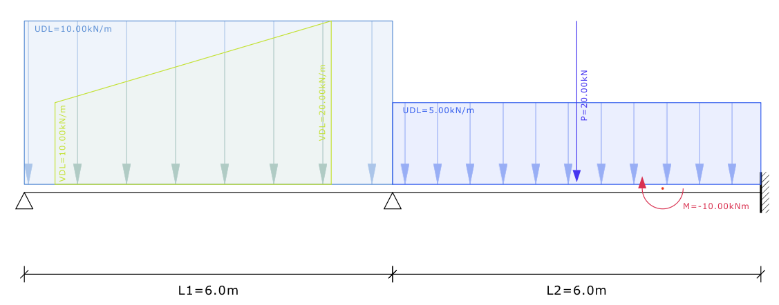
Input example for continuous beam
Assumptions
The following assumptions are considered in analysis:
Each span has a constant cross-section with uniform E and I over its full length.
The beam is assumed to not develop any excessive deflections (small-deflection theory applies).
Stresses are assumed to be elastic throughout.
Interior supports are rigid (no settlement). Left and right end supports are either pinned or fixed.
All loads entered are assumed to be at ULS and no factors are applied in the analysis.
The modulus of elasticity for steel is taken as E = 200,000 MPa for all spans.
Limitations
The calculation has the following limitations:
End support conditions are limited to pinned or fixed. All interior supports are treated as rigid pinned supports.
The number of spans is limited to a maximum of 10.
Steel sections are selectable from input dropdown and are not manually adjustable.
Load types are limited to uniformly distributed loads (UDL), variable distributed loads (VDL), point loads (PL) and moment loads (ML).
The number of loads per type is limited to 25 per load type.
| Input Variable | Description | Limits |
|---|---|---|
| Support (Left) | Support condition at left end | Pinned / Fixed |
| Support (Right) | Support condition at right end | Pinned / Fixed |
| n | Number of spans | n ≥ 1 |
| L | Span length | L > 0 |
| Section | Beam section designation | e.g., 406×178×74 |
| m | Beam mass per unit length | m > 0 |
| Iy | Second moment of area | Iy > 0 |
| msw | Include self weight in calculation | Yes / No |
| w | UDL intensity | w ≠ 0 |
| a | UDL start position | 0 ≤ a < b |
| b | UDL end position | a < b ≤ L |
| wa | VDL intensity at start | |
| wb | VDL intensity at end | |
| a | VDL start position | 0 ≤ a < b |
| b | VDL end position | a < b ≤ L |
| a | Point load position | 0 ≤ a ≤ L |
| P | Point load | P ≠ 0 |
| c | Moment load position | 0 ≤ c ≤ L |
| M | Applied moment | M ≠ 0 |
| Result Variable | Description |
|---|---|
| Ri | Reaction at support |
| Rmax | Maximum support reaction |
| Vmax | Maximum shear force |
| xVmax | Position of maximum shear force |
| Mmax+ | Maximum positive bending moment |
| xMmax+ | Position of maximum positive bending moment |
| Mmax- | Maximum negative bending moment |
| xMmax- | Position of maximum negative bending moment |
| θmax | Maximum slope |
| xθmax | Position of maximum slope |
| θmin | Minimum slope |
| xθmin | Position of minimum slope |
| δmax- | Maximum downward deflection |
| xδmax- | Position of maximum downward deflection |
| δmax+ | Maximum upward deflection |
| xδmax+ | Position of maximum upward deflection |
| L/δ | Deflection ratio (L/δ) |
Standards
None
References
- Walter D. Pilkey and Pin Yu Chang - Modern Formulas for Statics and Dynamics, A Stress-and-Strain Approach, McGraw-Hill (1978)
- Clapeyron, B.P.E. (1857) - Calcul d'une poutre élastique reposant librement sur des appuis inégalement espacés (Three-Moment Equation)
| Release Date | Version | Description |
|---|---|---|
| January 2024 | 1.0.0 | Initial release. |